Keer Zhao
Intro to Physical Computing
TOOL BOX
1.0 Arduino info

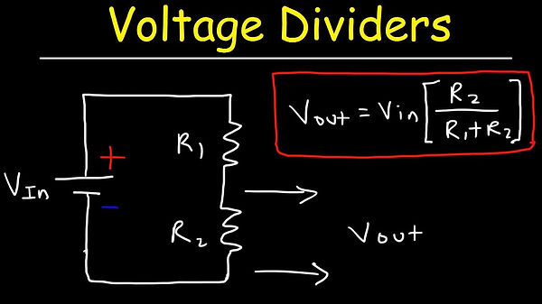
2.0 Voltage dividers
lab #1: digital input and output with arduino


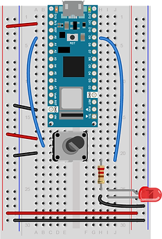
Digital Input:
Pushbutton
Digital Output:
Two LEDs
New Code I Learned:
-
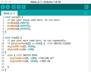
HIGH & LOW
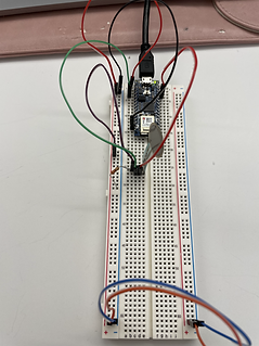
In the setup shown on the left, a digital input will be triggered by the pushbutton. 'HIGH' means there's a current, and the switch is closed, then the output will be sent to LEDs.
code
I intended to also try the same setup with two speakers. Luckily, I found two new speakers in the 'Junk Area'. But unluckily, those two speakers did not work. The reason for that is those speakers require an oscillating current, instead of a steady DC current.
This is a link to a similar project involving this kind of speaker and Arduino.
And btw, this website () has a lot of interesting Arduino projects.
Basically, PWM (Pulse Width Modulation) will convert the digital output into an analog output. By changing the duty cycle of PWM, an oscillating output will be created at a certain frequency (PWM pins produce signals at 490Hz or at 980Hz).
In order to make the speaker 'speak', I should also use tone( ), which I will learn more about in Week 3.

lab #2: ANALOG INput with arduino

Analog Input:
Potentiemeter
Analog Output:
Red LED
New Code I Learned:
*A way for Arduino to talk
*it sends out a PWM to one pin
I spent a lot of time thinking about this setup.
I was initially confused about whether the potentiometer is connected to the LED.
The gif actually shows that I thought, those two components are connected by intentionally adding a green line. However, the analogWrite command in my code is actually telling the LED to do things. Then I was so confused about if it's me that by twisting potentiometer to make the LED dim and light, or it's the Arduino board.
Now, the problem is solved. Two sides are NOT connected. The Arduino board detects the changing voltage of the potentiometer, then transforms it into another digital output.


with phototransistor
with force sensing resistor
Analog Input:
Potentiemeter,FSR
When a phototransistor or FSR is connected to Arduino as an output, by using Serial.print, I am able to see some number changes when I cover the light or apply force to the sensor.

*Question unsolved:
Left disgram illustrates when a phototransistor is connected. I wonder why the long end is connected to the ground, the short end is connected to the positive?
Possible answer:
The two ends of a phototransistor represent one emitter and one collector. Collector side is connected to the voltage supply; emitter side is connected to the base.
Different tyes of phototransistor will have different assignment to each leg (just like two diagrams shown below). It's unlike LED with a fix assignment that current flow from long leg to the short. In particular, the one I used in lab : "short leg goes to voltage, long leg to the ground".
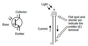
Diagram #1


Diagram #2


Description:
I remember I was actually very struggled with this section because I kept having the negative lightness value. So then I just left it there for that day.
The next day, I re-wrote the code, change the number:
float voltage = sensorReading * (5.0 / 1023.0)
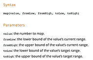
int lightness = map(sensorReading, 0, 1023, 0, 5)
It worked, but I forgot to take a screenshot...
The reason for the negative lightness should be 'out of range', possibly less than 100 (?), then what's converted into 0-5 scale, it is negative.
lab #3: Sensor change detection


"Detect a state change"


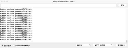


"Press Count"
Left shows the first time I try to count the press. The printed numbers are extremely high. The right shows that I add one line at the bottom to let buttonstate return to LOW. The reason for the left result is because the buttonstate is always HIGH so that it is kepting counting the times.
HOWEVER, everytime I push the button, it counts twice. I asked around of other people, they have the same issue. I think this is because, in the code, HIGH/LOW actually also mean a certain number. When I press and release the button, as the voltage drops during the releasing state, it is still comparatively higher voltage than the LOW. That's why, it double counts.
A way to fix this would be set a strict votage number for HIGH and LOW.

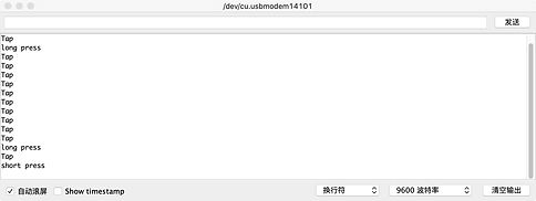
"Long press, short press"
Analog Input:
FSR
New Code I Learned:
*data type: long and unsigned long? what are they?
Description:
During the process, I missed a { sign after 'else', so the code did not run.
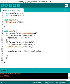

"Detect a peak"
There are in total 3 'if' statements.
* If there is no command after an 'if' statement, the computer will do nothing, right?
e.g. the second 'if' follows no instruction, then sensorValue less than the threshold will not be printed. But why is this 'if' necessary?
why not
if (sensorValue > peakValue) {
peakValue = sensorValue;
}
if (peakValue > threshold ) {
Serial.println(peakValue);
}
SAD : (
but why?
