Keer Zhao
Intro to Physical Computing
class notes
1.0
lab #1: TONE OUTPUT

Analog Input:
FSR
Analogu Output:
Speaker
New Code I Learned:
*tone(pin, frequency)
tone(pin, frequency, duration)


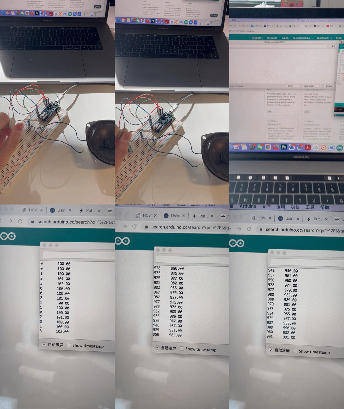
Pictues of Step 3


Setup of a transistor in a circuit
Step 1: FSR CHECK
Reading ranges from 0-1010.
Step 2: SPEAKER CHECK
It does make a sound!
Step 3: PLAY TONES
Also worked!
Left code and gif show that the analog input made by FSR is converted to analog output for the speaker with varying frequency.
Step 4: Amplifier
*Why transistors can be amplifier?
A transistor normally has three leads: base, collector and emitter. The collector will have no current is there is no current in the base. Considering the fact that base is usually 1% of the collector current, and two of them are directly proportional. An increase in base current, will result in a large increase in the collector current, this the final outputting current.
*Voltage remain constant, only current changes.


Image there is a little person inside the transistor that's always adjusting the collector out in order to satisfy
Ic = Ib * certain factor
This disgram is a typicall NPN transistor. As electrons flows to the collector side, there's also a tiny amount that flows to the base.
Step 5: Headphone
... lacking a audio jack...
Step 6: More complexed
Results shown on the right.
It sounds like game-over lol.


Step 7: An instrument

Goal:
When pressing different FSR, a different tone will be played out loud.
New Code I learned:
*for (initialization; condition; increment) {
}
Descriptions:
This time, I used the speaker from Week 2 (which did not work at that time) and it worked!
When I set this up, even when I was not pressing FSRs, the speaker plays a small noise. Then I set the threshold to be a higher number, the noise disappears and the speaker only makes the sound when I press it. I think the unwanted noise may come from some small current.


lab #2: Servo motor control


New Code I learned:
-
Servo library #include <Servo.h>
-
servoMotor.attach
-
servoMotor.write. //these two syntax are from the library I think
Descriptions:
On the analog side, I choose a phototransistor, the range is tested to be between 0 - 25. In the code part, I also intentionally put a delay to slow down the pace.
It seems like either when I completely cover it or it fully exposes, it will have the largest spin angle. When there is more light, it spins clockwise; when the environment gets dim, it spins counter-clockwise.
I like this motor, it looks cute.

*One extra question:
The 5V output on my Arduino board always does not work... why?